Yamaha MA-7 research and info
On this page I will collect all the info I have about Yamaha MA-7 (Mobile Audio 7, YMU786). You can find some info about MA-x series chips here.
You may also be interested in scarse community-made MA-3 registers datasheet, MA-3 research GitHub repo and the MA-3 tunes playback platform based on STM32F407-DISCOVERY board.
My contacts: Discord: ltva, Reddit: u/LTVA, email: gsaraykin at gmail dot com, Telegram: @g_caraykin, WeChat: Saraikin Georgii.
| Contents: |
|---|
| Overview |
| FM channels |
| PCM/ADPCM channels |
| Audio channels |
| Polyphony |
| DSP effects |
| Internal RAM |
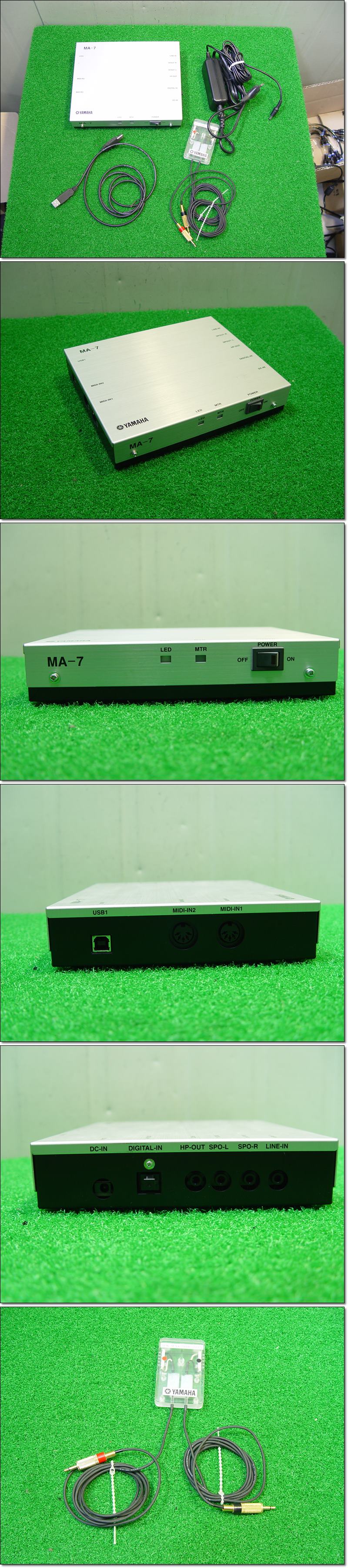
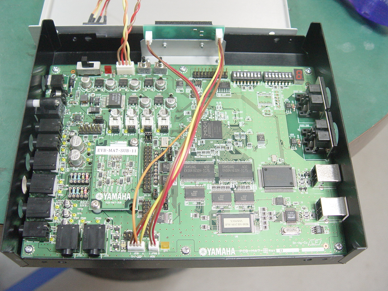
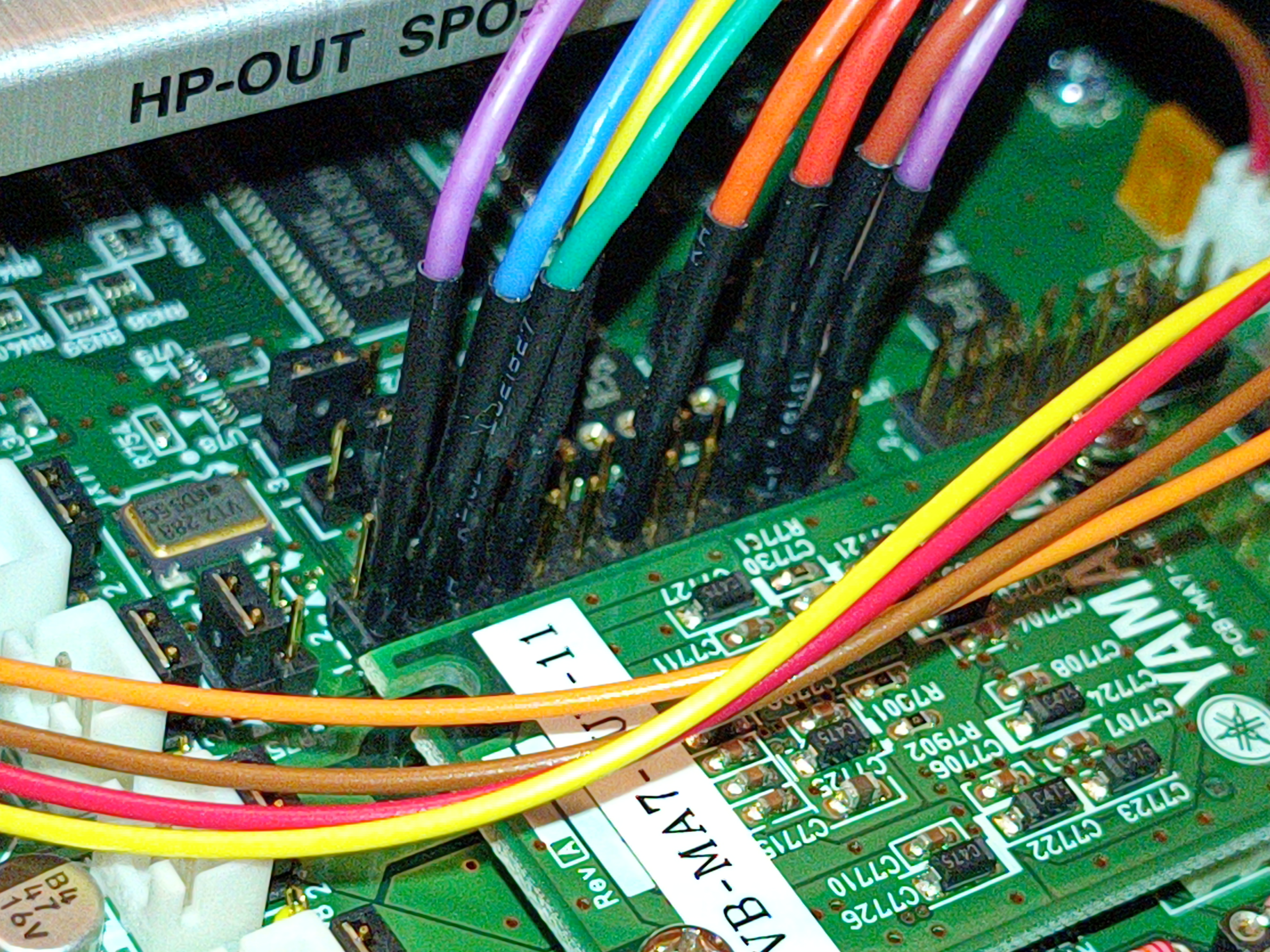
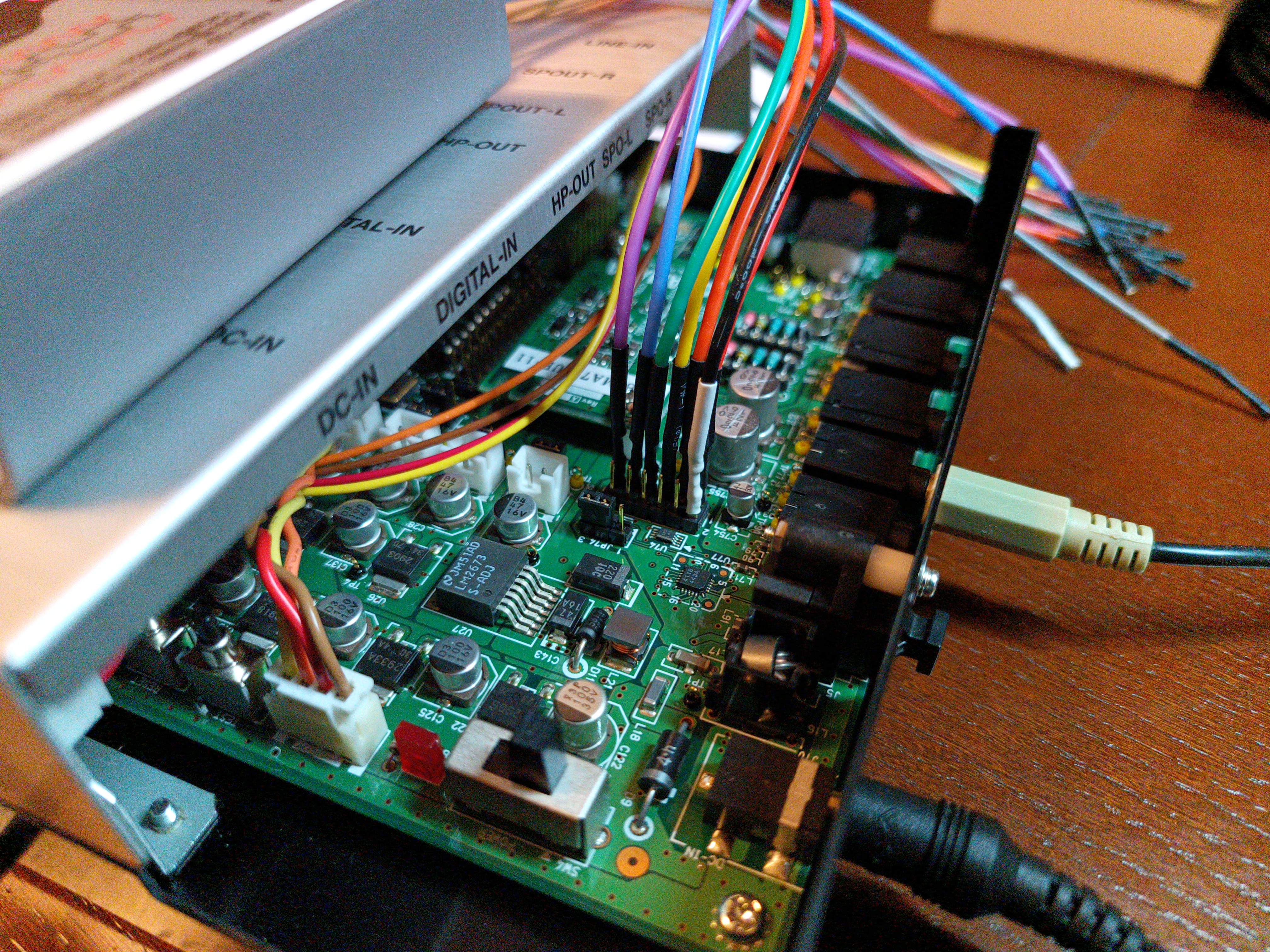
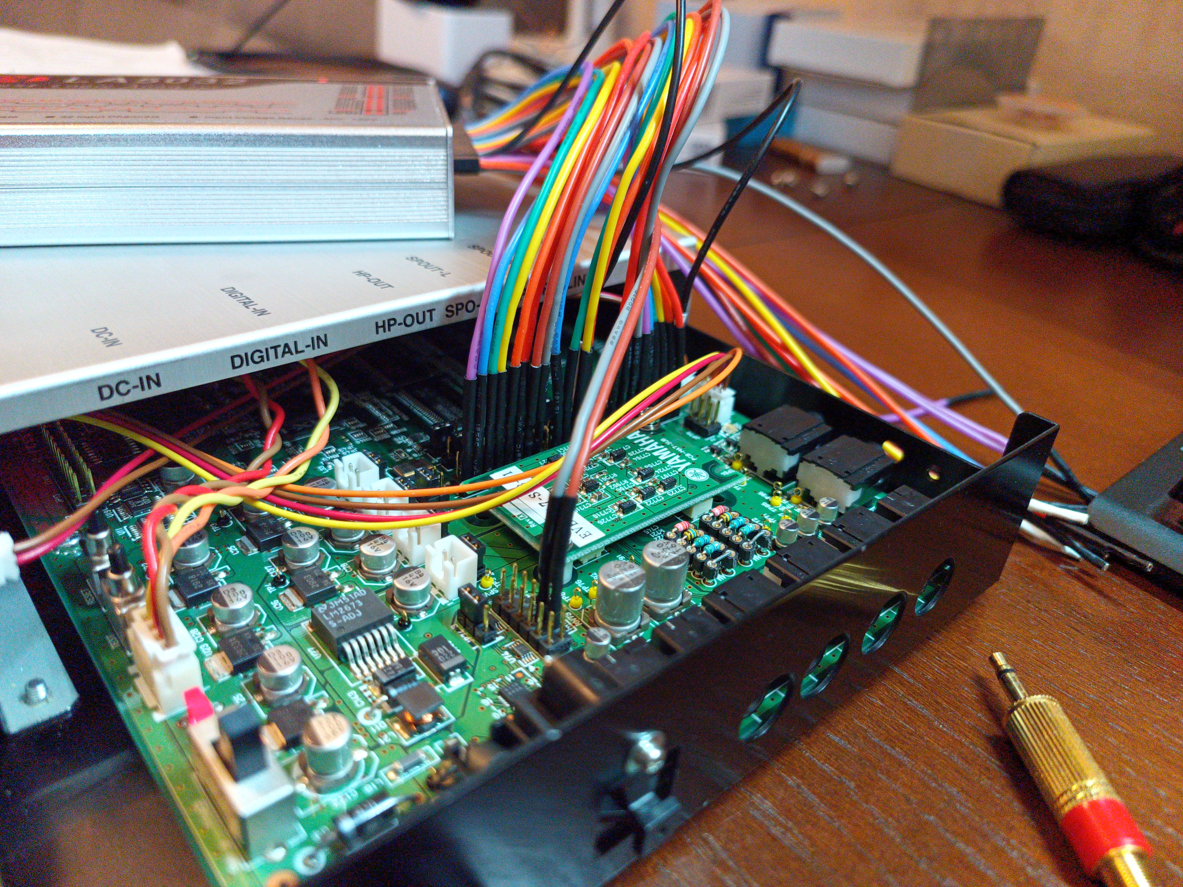
| Pictures of MA-7 development board |
| Pictures of my MA-7 development board |
| Research log |
Overview
Right now I don't have a way to directly interface real chip on the dev board, so everything you will see is info collected from MA-7 author tool. It's unclear which features are hardware and which are software. You can also try to decompile DLLs from MCP MA-7.
There also is a dump of the disk (which comes with dev board) contents (thanks @heemin!).
The chip features multi-channel diverse audio synth capabilities, has internal DACs, op-amps and stereo sound output. Possibly features internal PLL.
Yamaha claims up to 128 voices polyphony, but these probably aren't channels in chiptune sense (see below).
The chip's pinout can be found there (thanks @now_its_dark for finding this!). Here you can see the pinout, pin descriptions and high-level block diagram of the chip.
I received the board (thanks @heemin!), so soon I will hopefully succeed with the research and documenting phase.
FM channels
Chip has several FM channels. Each channel can be 4-op or 2-op (?) probably, like in OPL3, 2 2-op channels can be combined into 1 4-op channel. This totals to 32 2-op FM channels or 16 4-op FM channels. Each channel has 2 2-op and 6 4-op algorithms. Some algorithms feature feedback on two operators.
Each FM channel has 32-step panning.
Each FM channel has weird LFO selector, 0-3. It actually controls tremolo speed (AM speed) and vibrato speed (tremolo and vibrato seem to share this LFO speed). Each FM operator has a toggle for vibrato and tremolo, and 4-step control over tremolo and vibrato depth, although I could clearly hear only tremolo, vibrato was very shallow even at maximum depth.
Each FM channel has lowpass resonant filter with envelope. Resonance is 0-31, envelope has 5 points, for each cutoff control is 0-8184. Envelope has sustain flag and ignore key-off flag. Envelope has a simple cutoff scaling, "key follow", which increases cutoff for higher notes. Envelope rates are 0-31, there are 4 such rates, labeled AR, DR, SR and RR. Also LFO is present, its effect is combined with envelope. LFO has two shapes, triangle and semi-random (labeled as S&H?). LFO has 0-7 frequency and depth controls.
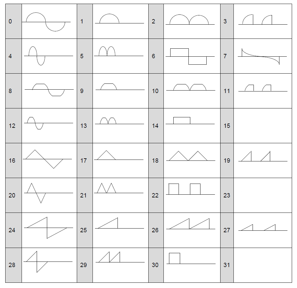
Each operator can be turned on and off (opmask?). Each operator has 32 waveforms to choose from, they are the same as on YMF825:
 |
|---|
| The circle segment-drawn waveforms are sine waves. |
Three missing waveforms are global RAM-stored waveforms you can specify. MA-7 author tool supports 16-bit PCM wav files and clamps them at 1024 samples length, so that's the format waves use.
Each operator has ADSR envelope with sustain rate. AR, DR, SR and RR are 0-31, sustain level is 0-15. Total level is 0-63. There are flags to enable sustain, to ignore key-off for envelope, to enable vibrato and tremolo. Vibrato and tremolo depth controls are 0-3. Each operator has KSR toggle (envelope speed) and 4-step key scaling level strength control (volume scaling). Feedback is 0-7 for those operators that have it. Detune is 0-15.
Each operator can be put in fixed frequency mode where operator's frequency can be independently set.
PCM/ADPCM channels
Chip seems to support 4-bit ADPCM, as well as 8- and 16-bit PCM samples. There are 32 PCM channels. Multiple PCM channels can share the same sample. You can specify "base" sampling frequency, as well as start and end of looped section (so it supports loop point). Volume envelope and filter block are identical with FM channel, as well as vibrato/tremolo/panning controls.
You can choose either MIDI bank sample (stored in chip ROM?? or loaded from phone memory), custom sample or noise for playback. Length of sample cannot exceed 16382 bytes.
PCM/ADPCM channel has pitch envelope. It is identical to filter envelope, but instead of cutoff control points are -127 to 127 and control relative pitch change (in semitones?). It doesn't have "key follow" flag.
Given the small size of internal RAM, most likely you would use these channels with wavetables. 32 256-byte wavetables total to 8 KiB of used RAM.
Audio channels
This seems to be the streamed audio section. It's unknown how exactly audio is streamed but seems like it requires external CPU or whatever to provide properly timed and generated PCM stream. MA-7 author tool provides 16 "Audio" channels, two last of them are used to playback 2 different ADPCM samples simultaneously in MA-7 authoring tool demo project. If you try to place playbacks of these samples on more "Audio" channels, all except two of them go silent. So the max number of simultaneously playing channels is two, at least in MA-7 authoring tool.
Vocaloid/speech synth channel
Chip has some speech synth capabilities. HV editor (HV probably stands for human voice) features point envelope (called "formant", shows frequency offset and volume?) and the array of 8 control blocks. Each block has the following settings: volume, frequency offset (signed, in cents), waveform (the same as in FM channel editor), 0-3 LFO speed, AM and vibrato toggles and 0-3 depth controls. There's also one "Prosodic Volume Enable" (sic!) checkbox in the editor.
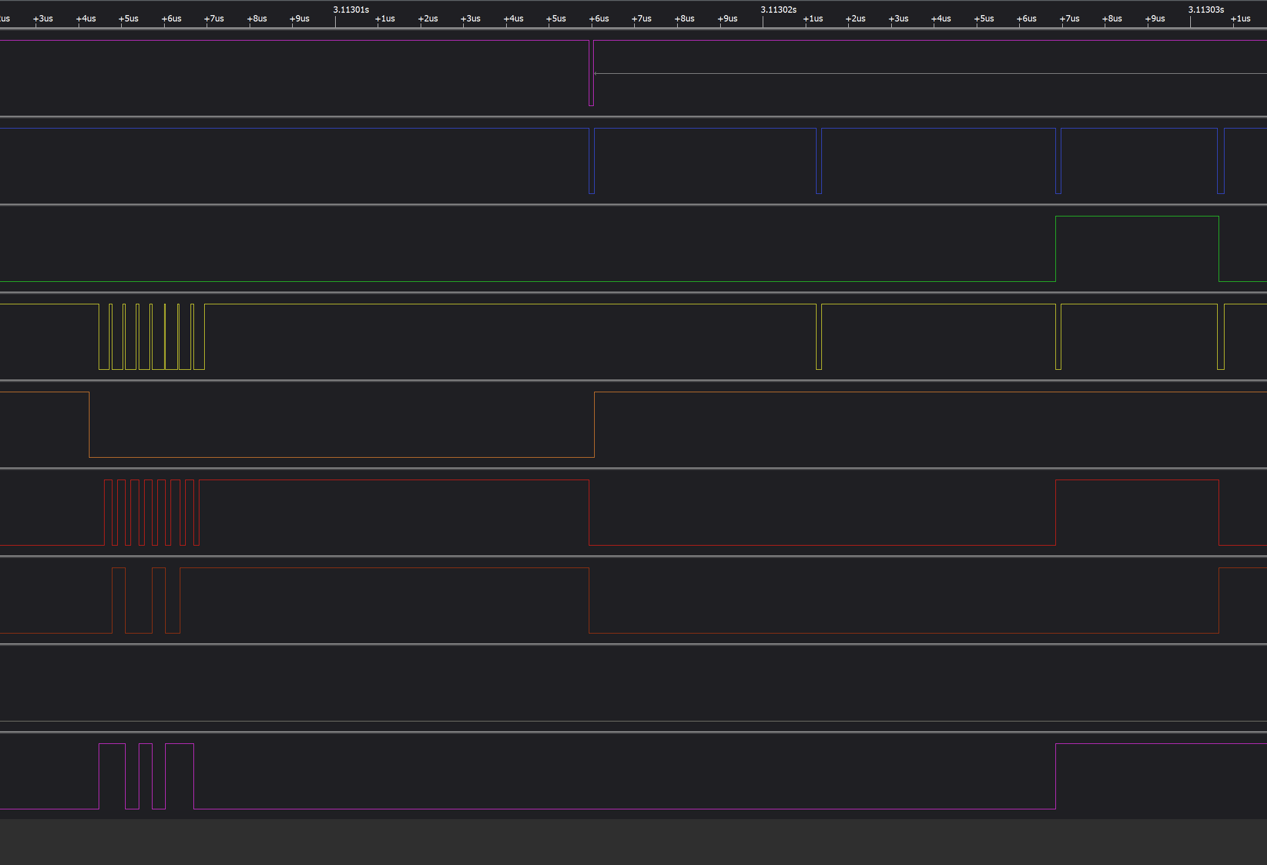
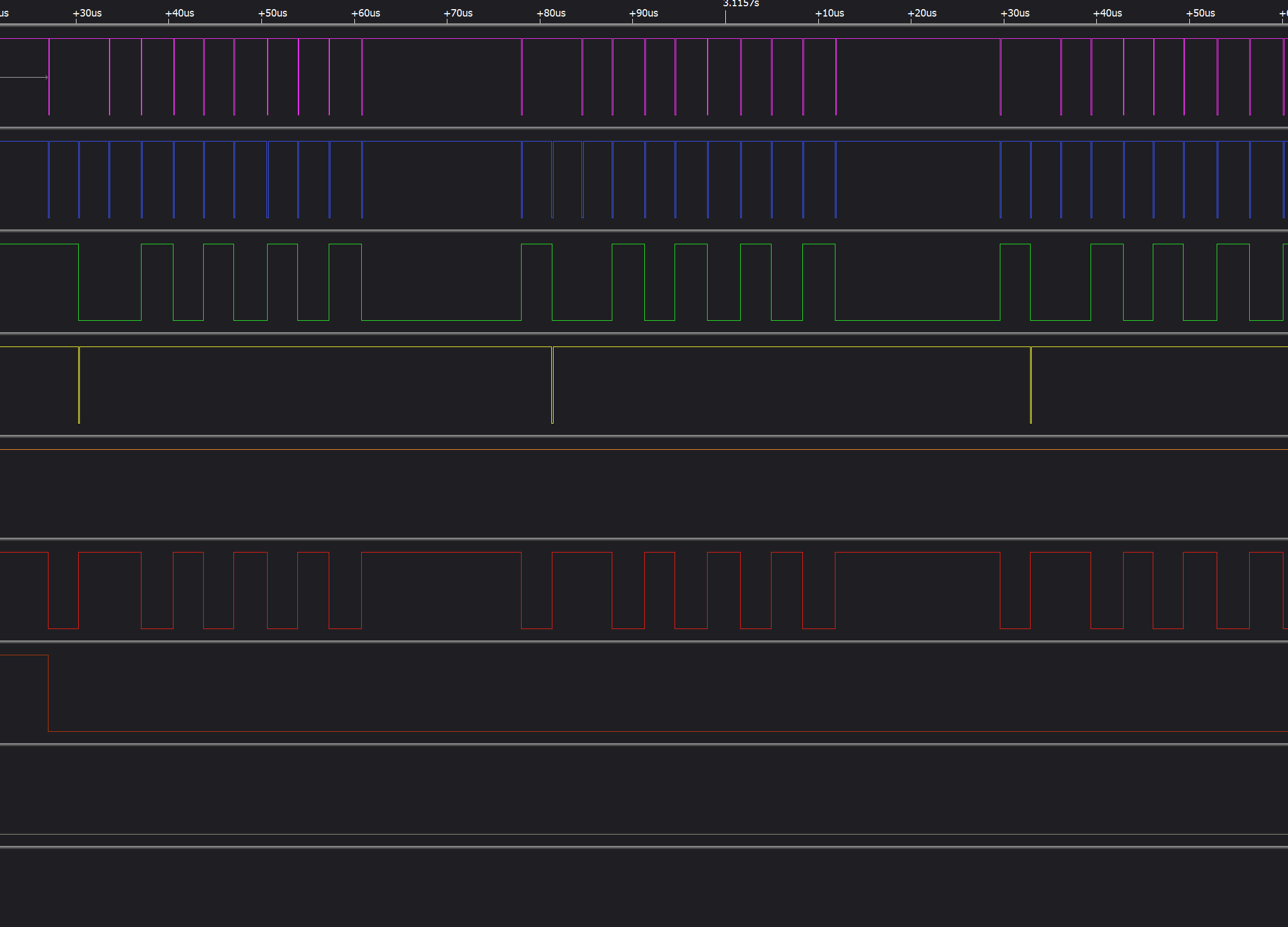
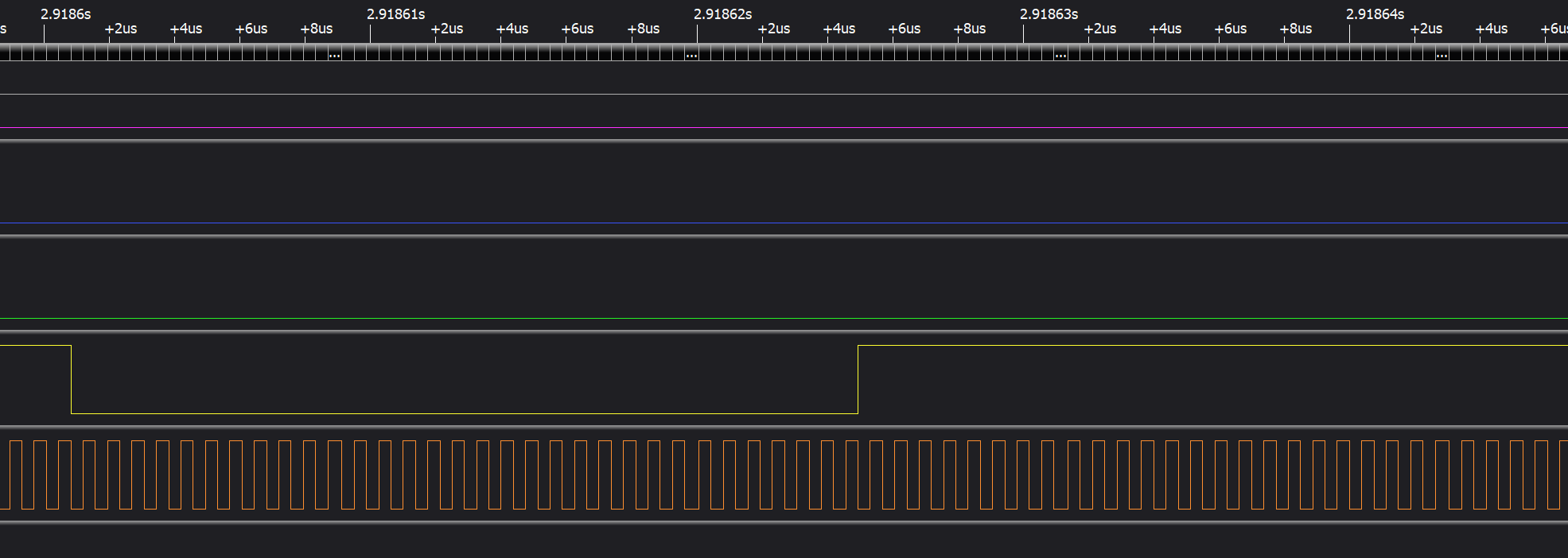
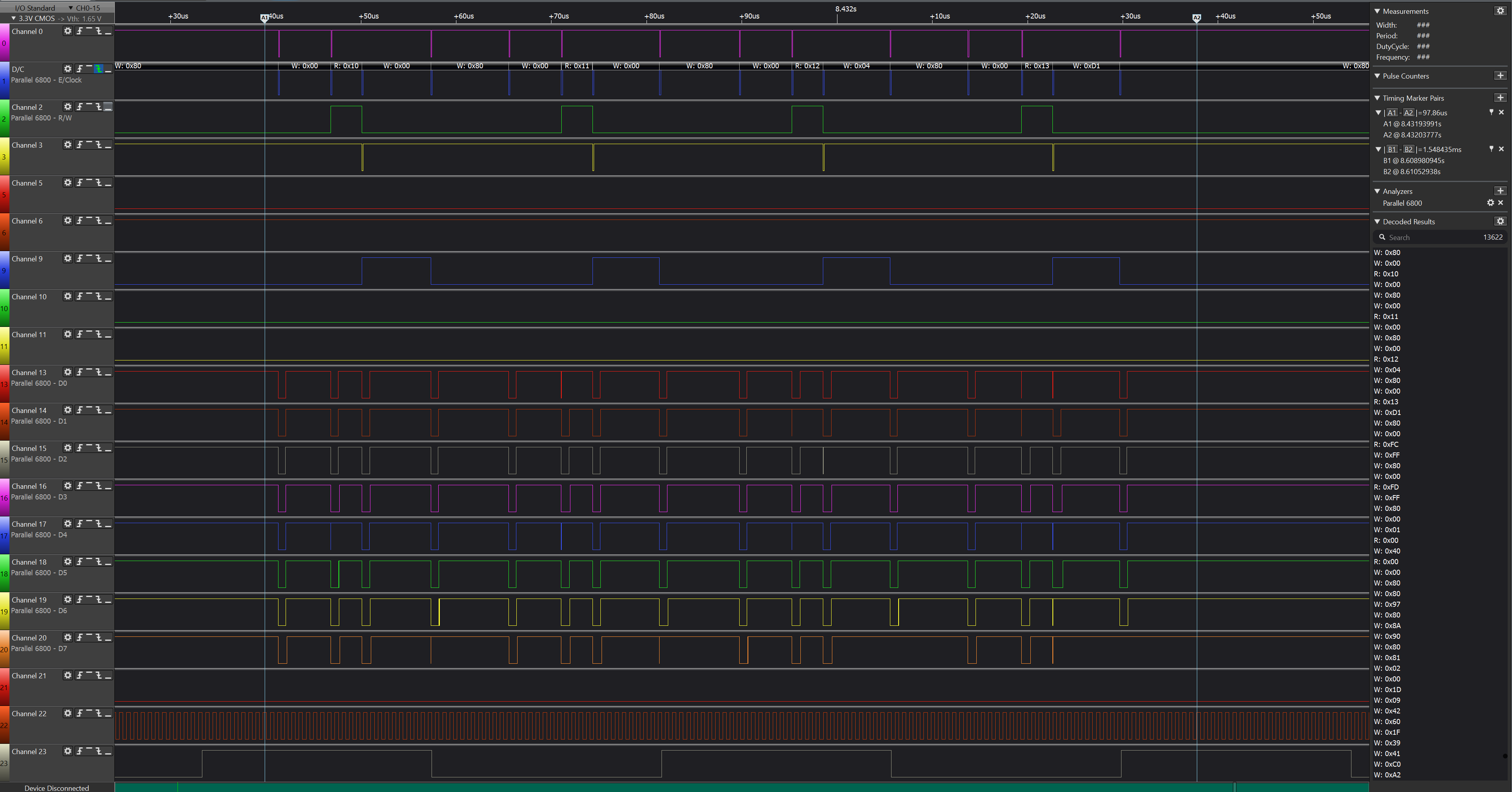
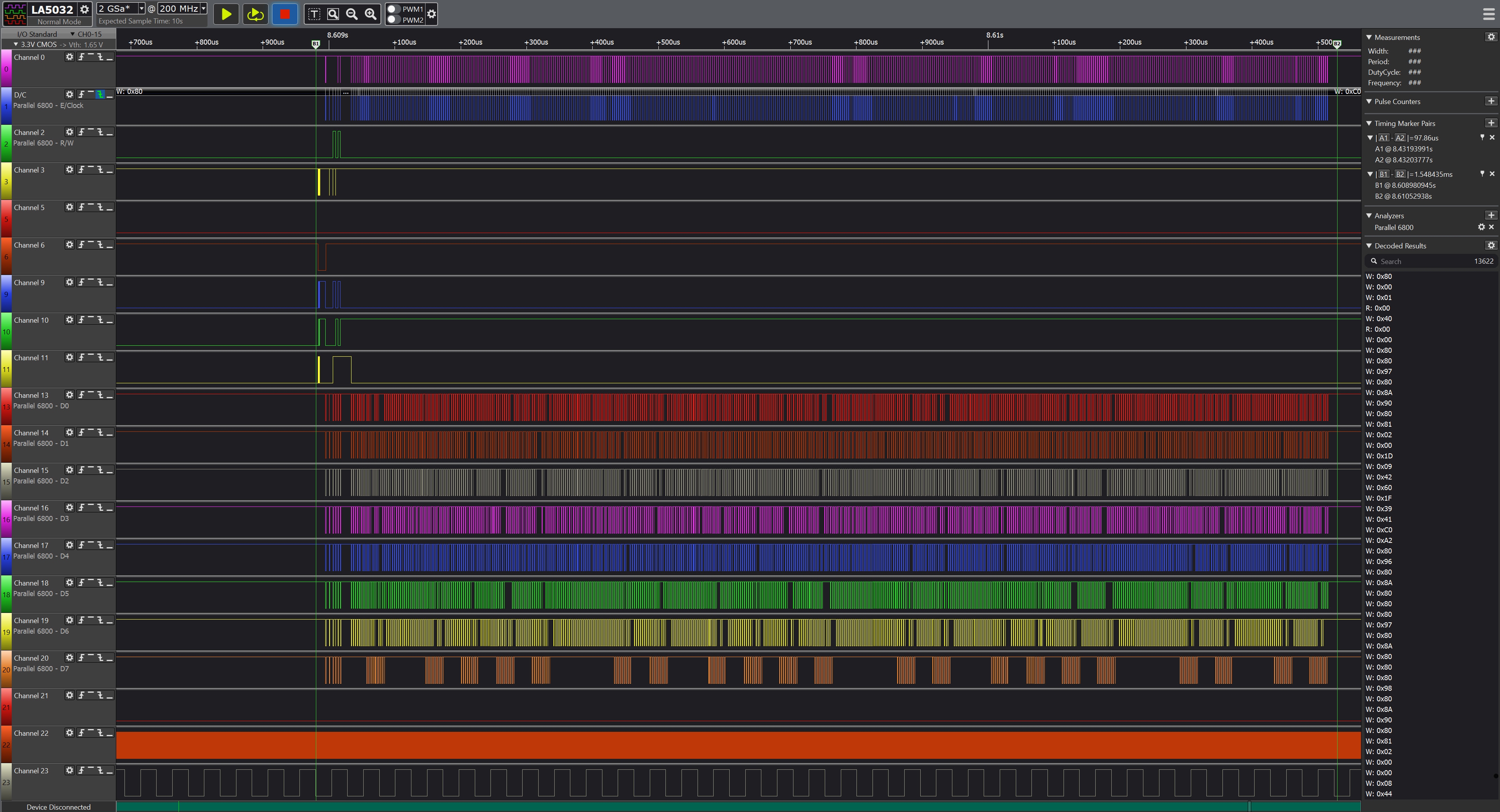
In the next editor you can specify what vocaloid says, using Japanese syllables and special symbols that control pitch, volume and "expression" (probably some filters?). The playback of speech synth script is probably handled in software since from recording register updates are at around 60 Hz rate.
Polyphony
Now it is unclear what's the speech synth implementation is. Waveform looks like it's CSM mode but for 8 operators. It is unclear if there are some dedicated hardware channels used for that or 4 2-op channels are put into some special mode to output CSM fundamental frequency + 8 of their own frequencies. There aren't any "noisy" syllables so probably no modulation is happening.
That's why it's unclear what Yamaha tried to say with "up to 128 voices". Since each FM operator has its own frequency control in fixed mode, PR/marketing team could just count FM operators, add in PCM/ADPCM channels and call it a 128 voices polyphony.
If chip really has 128 voices polyphony, then how? For example, it's known that MA-3 in 2-op mode has 32 FM channels. This leaves 96 channels. Let's assume that there are 32 more channels for PCM/ADPCM. You still have 64 channels for... whatever. So I think that it either has more FM channels, some of which are only for speech synth, or Yamaha was not correct there.
MA-7 authoring tool says that for MA-7 only "Normal" mode is supported. In manual it's said that mode supports 32 FM + 32 PCM + 2 Audio (streamed) + 1 HV (speech synth) channels. This totals up to 67 channels. Still not 128...
DSP effects
Each channel can have 2 DSP effects. In MA-7 author tool they are called "SFX1" and "SFX2". SFX1 takes mono input and produces stereo output. SFX2 takes stereo input, emits stereo output. This output is summed with SFX1 output (left and right channel separately), as well as both outputs are added to SFX1 input.
MA-7 author tool allows to choose one of the presets for SFX1 and SFX2 and modify some of their parameters. Parameters count and limits differ from preset to preset, apart from maybe LP/HP filters cutoff in several SFX1 presets.
SFX1 presets: room reverb, plate(?), karaoke(?), delay. You can also select "no effect".
SFX2 presets: chorus, celeste, flanger, tremolo, ringmod, auto-pan, phaser, distortion, overdrive, amplifier simulator, stereo 3-band equalizer, mono 2-band equalizer, 2-band equalizer, auto-wah, pitch change, compressor, voice cancel, ensemble detune, ambience. You can also select "no effect".
Internal RAM
AT-MA7-SMAF (authoring tool) user manual says that there are 16382 bytes available in MA-7 RAM. The manual also gives the info about how many bytes does channel info occupy: 22 or 38 (?) bytes for 2-op FM channel, 42 or 58 (?) for 4-op FM channel, 14 or 30 (?) for PCM channel without "PEG" (without pitch envelope generator data?), 40 or 40 (sic!) (?) for PCM channel with "PEG". Most probably the differences are in if filter envelope data is added, since for 2-op & 4-op FM and for PCM without "PEG" the size difference is constant (16 bytes). However, the PCM channel with "PEG" data breaks this logic (maybe a mistake/typo in manual?).
Sample occupies the number of bytes it weighs if size in bytes is even and (size + 1) bytes if size is odd (rounded upwards to nearest 2-byte boundary). Custom FM operator waveform weighs 2048 bytes which perfectly matches with the 1024-steps restriction given that each step uses 2 bytes.